Motion Tracking in Blender 5.2: Put 3D Objects into Real Footage Step by Step

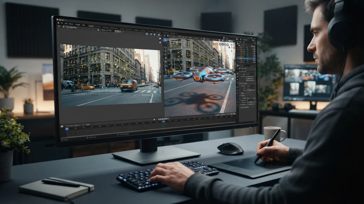
Motion tracking in Blender 5.2 LTS turns a phone clip into a 3D scene with a solved camera: high-contrast markers, the Solve button, a grounded floor, and the Movie Clip node so your model follows the footage's perspective.
What Motion Tracking Is and Why Blender 5.2 Is a Serious Contender
Motion tracking follows high-contrast points in the video (the markers) to calculate the camera's movement and, with that information, place 3D objects that blend into the footage. For years that meant opening After Effects or Nuke; Blender ships it built into the Clip editor, and the 5 series has turned it into a production-grade workflow, with camera and object tracking without switching applications.
The Rebuilt Tracking Engine of the Blender 5 Series
The Blender 5 series introduced a completely rebuilt tracking system that, according to the community itself, marks a before and after in motion analysis for integrating digital elements. Back in 5.0 it already received visible improvements, such as theme colors for velocity axes and reprojection error curves in the Graph View, and 5.2 keeps that engine as a stable base.
5.2 LTS: Supported Until July 2028 for Production Pipelines
Blender 5.2 LTS was released on July 14, 2026, and will receive maintenance updates until July 2028. For a VFX pipeline that matters: you can build a tracking, compositing, and rendering workflow knowing the version will not move for two years. On top of that, 5.1 upgraded the VFX platform 2026 libraries (Python 3.13, OpenColorIO 2.5, OpenEXR 3.4, and OpenVDB 13.0).
Read also
Preparing Your Footage Before Opening Blender
The best tracker in the world cannot fix a poorly shot clip. Preparing the footage is half the result.
What Makes a Good Clip: Full HD, 24-30 FPS, Shallow Depth of Field
A clip at 1920x1080 and between 24 and 30 fps is the sweet spot: enough resolution for the markers to have detail and smooth movement from frame to frame. Avoid heavy motion blur, sudden exposure changes, and repetitive low-contrast textures. The sharper and more distinct the points the camera travels through, the easier the solve will be.
High-Contrast Points: The Raw Material of Markers
Markers cling to corners, window edges, signs, or cracks: any point where brightness changes clearly. A flat wall offers nothing to follow; a frame corner does. Before shooting you can even prepare the real scene: sticking high-contrast paper marks where the 3D model will be anchored makes tracking and the later floor orientation much easier.
The Workflow in the Motion Tracking Workspace
Blender ships a dedicated workspace, Motion Tracking, that organizes the Clip editor views. The basic flow: open the clip, detect features, refine markers, track, and solve.
Opening the Clip and Auto-Detecting Features
In the Motion Tracking workspace you open the clip from the Clip editor menu and hit Detect Features. Blender analyzes the frame and proposes candidate points distributed across the image, marked with arrows showing their direction of movement. Not all will be useful: delete the ones in low-texture areas or the sky and keep a reasonable spread across the whole image.
Placing and Refining Markers by Hand (Ctrl + Left Click)
On top of the automatic features, or instead of them, you place markers with Ctrl + Left Click on the point to follow. Each marker has a search area that defines where the tracker will look on the next frame: larger for fast movement, smaller for precision. Choose points that stay visible and stable for as long as possible across the clip.
Tracking the Sequence and Reviewing Curves in the Graph View
With the markers placed on the first frame, you press Track Motion (or Ctrl + T) and the operator follows the selected features frame by frame; if it fails on some, it disables them and continues with the rest instead of stopping. Afterwards review the Graph View, where each marker draws its trajectory: smooth curves indicate clean tracking, and sharp jumps reveal a marker that escaped and needs re-placing.
Solving the Camera: The Solve Button and the Solve Error
With the tracking complete, the Solve button computes the camera's position and orientation on every frame from the markers. This is the moment of truth, and it has its own quality indicator.
Reading the Solve Error: Below 0.3 px Is Ideal, Above 1.0 Is a Problem
The solve error measures the average discrepancy between the markers' predicted positions and their actual positions in pixels. Below 0.3 px is considered a good solve; between 0.3 and 1.0 is acceptable; above 1.0 px something is wrong and you should review before continuing: poorly placed markers, too few on screen, lens distortion, or too much blur. A high error is not fixed by pressing Solve more times: it is fixed by improving the markers.
The Tripod Checkbox for Cameras That Only Rotate
If the camera was fixed and only rotated (a tripod, for example), enable the Tripod checkbox in the Solve panel. The solver assumes there is no translation and simplifies the math, which usually drops the error noticeably in that kind of shot. For handheld or dolly moves, it must stay off.
Lens Calibration: Manual Lens Calibration and Distortion
Phone lenses and wide angles distort the image, and that distortion contaminates the solve. If the error is high and the clip shows visible curvature at the edges, use the Manual Lens Calibration section of the Clip editor: you adjust the distortion value while watching the scene lines, and Blender compensates for the lens in the calculation. A few minutes of calibration can lower the solve error more than any other fix.
Orienting the Scene: Floor, Origin, and Axes
A solved camera still does not know where the floor is. Orienting the scene is the step that turns a cloud of points into useful coordinates.
Setting the Floor with Three Markers and the X/Y Axis
With the Floor button you select three markers on the same real plane (for example, three corners of the ground) and Blender defines that plane as the scene's floor. Then you adjust the X/Y axis so the orientation matches the shot, and you scale the scene using the real distance between two markers: if they are 2 meters apart in reality, the scene ends up at 1:1 scale. Only then does the 3D object sit on the plane at its correct size.
The Classic Mistake: Objects Sliding Across the Floor
The classic failure is the 3D object "floating" or sliding across the floor instead of staying anchored. The cause is almost always poor orientation: a floor plane defined with markers that are not actually aligned, or an incorrect scale. If the object shifts slightly as the camera turns, review the solve; if it slides consistently, review the floor and the scale.
From Clip to 3D Scene
Once the camera is solved and the scene is oriented, Blender lets you create the 3D scene from the tracking itself: the clip becomes the background and the solved camera becomes the scene's camera.
Creating the Scene from the Track and Adding the 3D Object
With Setup Tracking Scene, Blender generates a new scene with the footage as background and the camera already animated. From there you work as in any scene: add your model (an extruded logo, a low-poly ship), place it on the floor plane, and scale it to fit the reference. The camera already moves following the real shot, so the object is seen from the correct perspective without animating anything else.
Lighting and Scaling So the Object "Lives" on the Ground Plane
The object only looks real if its lighting and scale respect the clip. Study where the light comes from in the footage (shadows, floor highlights) and place scene lights in that direction; generic lighting gives the integration away instantly. For scale, measure real objects in the clip: if a parked car takes up that much in the video, your model must take up proportionally the same. With the floor at 1:1 scale, this is nearly automatic.
Compositing with the Movie Clip Node
The last step is the compositor: combining the 3D render with the original video so the seam does not show. The Movie Clip node is the piece that connects the tracking to the final render.
The Image, Alpha, and X/Y Offset Outputs of the Node
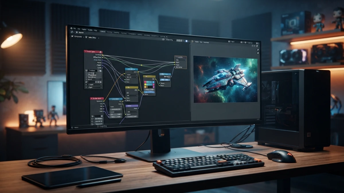
The Movie Clip node has no inputs and exposes as outputs Image (the clip's frame), Alpha (its transparency channel), and the X/Y offsets of the footage's camera. In the compositor you connect the scene render over Image, and use Alpha and the offsets to align and crop the exact frame. The result: the 3D object appears in front of the real video, following its movement and perspective. It fits with the compositing workflow already covered on the blog.
Final Render and Clip Stabilization
Before the final render, review the whole sequence: look for frames where the object loses contact with the floor or where a visible marker gives the tracking away. If the clip is shaky, Blender lets you stabilize the shot from the Clip editor (the analysis uses the same markers), so the final render comes out steady. And if you are going to publish the result on the web, the model and scene can be exported to glTF/GLB, as covered on this blog.
Troubleshooting: High Solve Errors and Lost Markers
If the solve error stays above 1.0 px, run through the list in order: markers on high-contrast, stable points; coverage across the whole image; less motion blur; lens calibration when there is distortion; and Tripod only when the camera does not translate. If markers get lost mid-sequence, go back to the frame where they escaped, re-place them, and re-track from there; the Track Motion operator disables the failed ones and continues with the rest. And if the object slides across the floor, the problem is not the tracking: it is the orientation or the scale.
Conclusion
Motion tracking in Blender 5.2 turns a phone clip into a 3D scene with a real camera in a few steps: shoot footage with contrast, place markers, solve the camera while watching the solve error, orient the floor, and composite with the Movie Clip node. With the LTS version guaranteed until 2028, now is the time to build that VFX pipeline without leaving Blender.